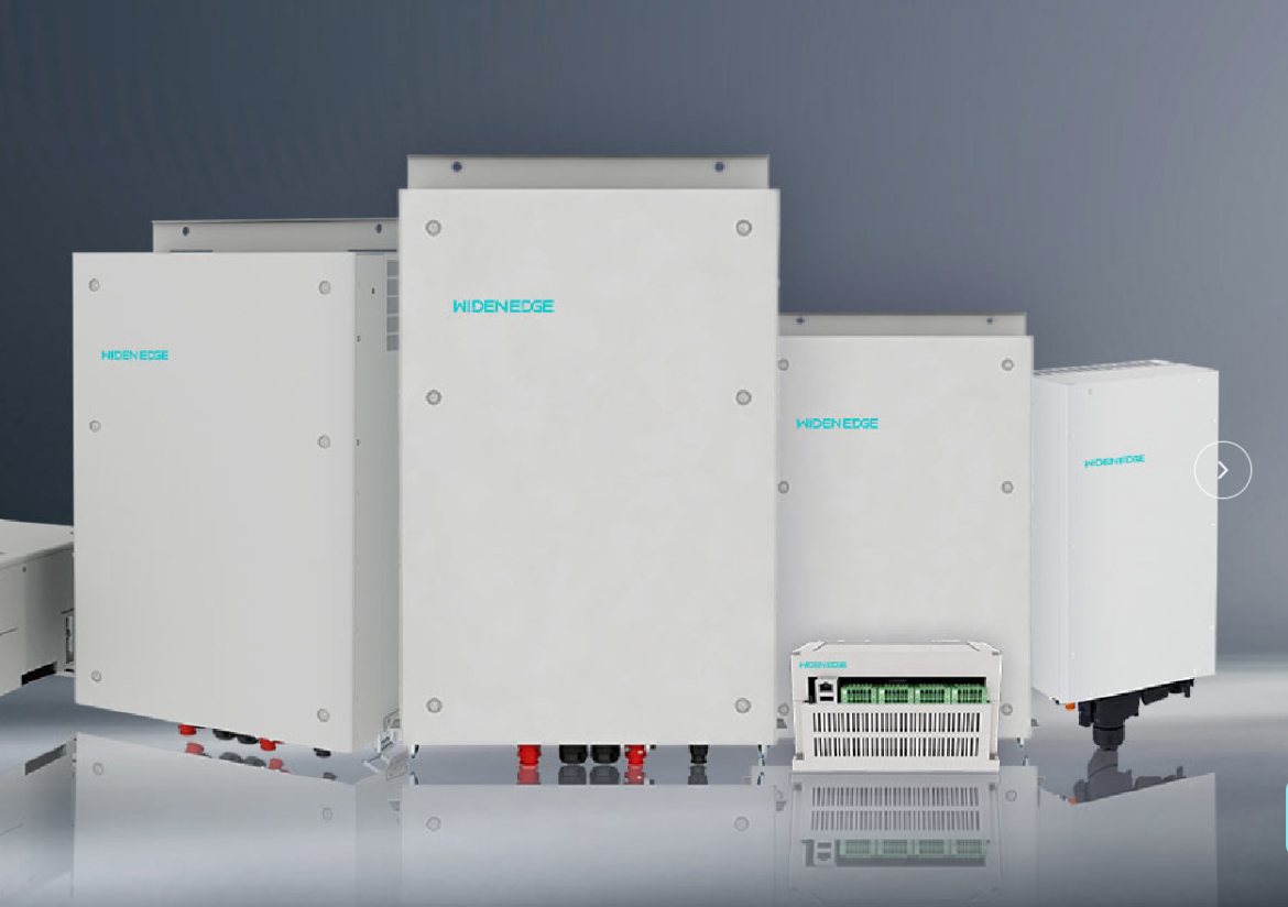
Immediate problem: why promising systems fail at commissioning
Please consider the frequent scenario: a well-sized solar array and battery bank are ready, yet the system becomes unstable or refuses to island cleanly during commissioning. This guide addresses that concrete failure mode for projects deploying a 100kW grid-forming inverter, explaining why planners must treat control behavior, protection, and testing as primary design variables rather than afterthoughts.
Core technical issues that cause integration failure
Polite clarity is useful here: these problems recur across sites and deserve specific attention.- Control-mode mismatch: grid-following inverters assume a stiff grid; grid-forming units must provide voltage and frequency reference. Confusion between modes leads to power oscillations.- Protection miscoordination: relay settings tuned to the utility grid can trip during intentional islanding.- Frequency/voltage droop and sharing: improper droop gains create poor load sharing or hunting between sources.- Black-start capability gaps: not all inverters are tested for reliable island formation under load.- Communication and telemetry gaps: lack of deterministic comms causes delayed setpoint changes and unsafe transitions.Standards such as IEEE 1547 and UL 1741 SA inform these areas; adherence reduces risk but does not replace site-specific engineering.
Stepwise design approach to resolve the problem
Follow these steps with methodical attention to detail:- Site survey and dynamic modelling: characterise source impedance, common-mode harmonics, and the expected three-phase unbalance.- Define primary control responsibilities: decide which assets will be grid-forming, grid-following, or hybrid before specifying droop settings.- Size and rating checks: confirm inverter continuous and short-term overload ratings relative to peak inrush loads.- Protection coordination plan: document relay curves, reclose logic, and island detection thresholds.- Simulation and HIL testing: replicate the site scenario in software-in-the-loop or hardware-in-the-loop to validate transitions and protection.- Commissioning script and acceptance tests: include black-start, seamless islanding, anti-islanding, and load sharing tests with pass/fail criteria.When selecting equipment, compare a vendor’s field-proven behaviour for black-start and droop sharing — a proper grid‑forming microgrid inverter should publish test reports or commissioning logs.
Practical configuration details to enforce during procurement
Please require the following from suppliers and contractors:- Deliver default control parameter sets and documentation for recommended droop coefficients.- Provide firmware versions with change logs and verification of anti-islanding algorithms.- Supply a deterministic communication option (e.g., Modbus TCP with QoS or IEC 61850) for tight control loops.- Offer factory acceptance test (FAT) reports showing black-start and load-sharing under representative conditions.Requesting these details up front saves weeks at commissioning.
Common pitfalls and how to avoid them
Address these recurring mistakes directly:- Mistake: assuming grid-following settings will work once batteries are present. Fix: designate and test a grid-forming source early.- Mistake: using default relay settings from the utility. Fix: coordinate with the utility and run protection coordination studies.- Mistake: skimping on transient models. Fix: run time-domain simulations for worst-case switching and load steps.- Mistake: neglecting human factors—operators without clear procedures. Fix: produce concise operator checklists and training runs.
Commissioning checklist that solves the problem rather than documents it
Please use this actionable checklist during on-site commissioning:- Verify inverter firmware and control mode matches design documents.- Execute black-start under predefined load steps; measure frequency and voltage ramp rates.- Perform intentional islanding with step loads to confirm droop sharing and stability margins.- Test protection coordination: overcurrent, under/overfrequency, and reconnection logic.- Confirm communications, telemetry, and remote-control fail-safes.Record measured responses and compare with pre-commissioning simulation outputs; require remedial tuning if deviations exceed agreed thresholds.
Field insight from a relevant deployment
Experience shows patterns repeat. A series of pilot demonstrations in Masdar City, Abu Dhabi, emphasised that early definition of control hierarchy and a compulsory HIL validation prevented repeated trips during islanding tests. That single geographic example underlines a broader truth: practical verification of control and protection behaviour on representative systems prevents schedule slip and warranty disputes.
Conclusion — a clear resolution for planners
The problem-driven path is simple: identify the specific failure modes your project faces, design controls and protection to neutralise them, and validate with realistic tests. Planners who insist on documented behaviour for black-start, droop sharing, and protection coordination will reduce commissioning risk and operational surprises. For teams that prefer a supplier able to deliver documented test evidence and on-site support, consider partners whose engineering deliverables and field reports match the technical expectations outlined above, such as WidenEdge.