
User-first opening: what this guide gives you
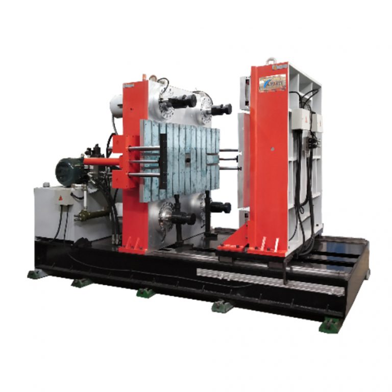
This piece is for product teams and shop-floor folks who need a clear path from prototype to a steady robotic overmolding line. I write from a practical, experience-based angle — EEAT: hands-on guidance shaped by integrations I’ve seen in Detroit-area automotive plants — so you’ll get actionable steps rather than vaporware theory. Start by considering a reliable horizontal rubber injection molding machine as your process backbone; that physical layout alone changes how tooling, robot reach, and cycle time are planned.
How user needs shape equipment choice
Users care about repeatability, footprint, and part complexity. Horizontal machines make robotics simpler: the platen and mold face align with robot approach paths, reducing awkward gripper motions and lowering scrap. Key terms here are clamping force and shot size — pick a machine whose clamping and injection unit match your part geometry and LSR viscosity. A modular cell with a dedicated conveyor or pick station speeds takt times without overcomplicating controls.
Designing the cell: robotics, tooling, and controls
Start by matching your robot’s payload and reach with the mold layout. Keep fixturing robust but accessible — quick-change plates help when you switch SKUs. Integrate safety gates and light curtains into the PLC so cycle time doesn’t suffer. If your budget allows, specify a servo-driven injection unit to stabilize shot consistency; consistent shots mean fewer post-process adjustments. Also consider a centralized vacuum for pick-and-place reliability, and align ejection to the robot’s wrist orientation for minimal wrist articulation.
Common mistakes teams make — and how to avoid them
Teams often under-spec the gripper and overcomplicate the mold. Don’t do both. Too-small grippers lead to dropped parts; oversized grippers add inertia and extend cycle time. Tooling that obstructs robot access is a frequent nuisance — design access paths first, then the mold. — Plan for maintenance access on day one; cramped cells kill uptime faster than any supplier delay.
Comparing horizontal and vertical layouts for overmolding
Horizontal cells win on robot ergonomics and inline automation. Vertical presses can save floor space but often force complex end-of-arm tooling and multi-axis pickups. Weigh factors like shot size stability (horizontal tends to give more consistent melt flow for certain LSR formulations) and mold cooling routes. If you need to dial in tight tolerances at scale, a horizontal layout paired with a synchronized robot and conveyor usually gives cleaner cycle times and easier diagnostics.
![]()
Integration checklist before you buy
Use this short checklist on site acceptance: – Confirm clamping force and injection unit match parts; include shot-size margin. – Validate robot reach and payload with the actual mold installed. – Run a 24-hour test to spot thermal drift or adhesive transfer issues. These steps catch mismatches that show up only under continuous run conditions.
How suppliers and brands differ — practical comparisons
Some suppliers bundle complete cells; others sell machines and expect integrators to build the rest. A supplier that offers pre-engineered interfaces for vision, feeding, and end-of-arm tooling reduces integration risk. If you want direct sourcing for the core press but still need integration help, look for partners that publish clear specs for I/O, axis signals, and emergency stops. Also note: a dependable horizontal injection machine with good documentation makes commissioning far less painful.
Three golden rules for choosing the right setup
1) Prioritize match over margin: select clamping and injection specs that closely match your largest and smallest parts rather than one-size-fits-all machines. 2) Validate real cycle time under production conditions — thermal effects and robot cadence change theoretical numbers. 3) Demand clear integration documentation and a supplier willing to test full parts in their lab before shipping.
That’s the practical edge: pick the right horizontal layout, confirm robot and tooling compatibility, and run real-world verification — then the line hums. HWAYI. —